SCREW COMPRESSORS FOR LASER PROCESSING SYSTEMS (15-75KW) | ProductID:041
Airpol LaserTech screw compressors are engineered specifically to deliver high-pressure, premium-quality compressed air required for precision laser cutting, engraving, and marking applications.
 Key Features & Benefits: Key Features & Benefits:
1) Premium Air Quality (ISO 8573-1 Class 1.4.1)
Equipped with an integrated refrigerated dryer and a 3-stage filtration system to eliminate moisture, dust, and oil aerosols—extending the lifespan of laser optics and cutting heads.
2) Variable Speed Drive (VSD) Technology
Features an integrated inverter that adjusts motor speed (50% to 100%) to match real-time demand, delivering up to 30% energy savings and ensuring stable system pressure.
3) Ultra-Speed Function
Allows smart adjustment of operating pressure ranges (13–16 bar or 16–19 bar, depending on the model), providing up to 15% higher air delivery (FAD) at lower pressures.
4) Intelligent Management (Airpol Power Control)
Features NAVI and OPTI controllers with color displays, capable of sequencing up to 4 compressors without cloud dependency to ensure maximum industrial cybersecurity.
5)Remote Monitoring (Web Server):
Provides secure, real-time access to operating parameters, maintenance counters, and event logs via any standard web browser over the local network (LAN).
Models:
1) Variable-Speed Compressors, Max. 1.9 MPa (19 bar)
2) Variable-Speed Compressors, Max. 1.6 MPa (16 bar)
3) Fixed-Speed Compressors
|

|
Variable-Speed Compressors, Max. 1.9 MPa (19 bar)
Model |
Product ID |
Capacity 16 (bar) |
Capacity 17 (bar) |
Capacity 18 (bar) |
Capacity 19 (bar) |
Nominal Power [kW] |
Dimensions (L × W × H)[m] |
Air Receiver [l] |
Air Purity Class (ISO 8573-1) |
KTPR 15 LaserTech |
0410 |
28-82 |
78-28 |
75-28 |
70-28 |
15 |
1.65×0.6×2 |
500 |
1.4.1 |
PRT 22 LaserTech |
0412 |
119-54 |
116-54 |
112-54 |
104-54 |
22 |
1.46×1.3×0.72 |
----- |
1.4.1 |
PRT 30 LaserTech |
0413 |
162-50 |
157-50 |
154-50 |
143-50 |
30 |
1.46×0.9×2.3 |
----- |
1.4.1 |
PRT 45 LaserTech |
0414 |
240-102 |
239-102 |
238-102 |
220-102 |
45 |
1.46×0.9×2.3 |
----- |
1.4.1 |
PR 75 LaserTech |
0415 |
438-186 |
429-186 |
420-186 |
402-186 |
75 |
1.67×1.23×2.1 |
----- |
----- |
Variable-Speed Compressors, Max. 1.6 MPa (16 bar)
Model |
Product ID |
Capacity 13 (bar) |
Capacity 14 (bar) |
Capacity 15 (bar) |
Capacity 16 (bar) |
Nominal Power [kW] |
Dimensions (L × W × H)[m] |
Air Receiver [l] |
Air Purity Class (ISO 8573-1) |
KTPR 15 LaserTech |
0416 |
54-96 |
54-91 |
54-86 |
54-82 |
15 |
2×0.6×6.45 |
500 |
1.4.1 |
PRT 22 LaserTech |
0417 |
54-142 |
54-133 |
54-126 |
54-119 |
22 |
7.2×0.3×4.6 |
----- |
1.4.1 |
Fixed-Speed Compressors
Model |
Product ID |
Capacity 16 (bar) |
Capacity 18 (bar) |
Capacity 19 (bar) |
Nominal Power[kW] |
Dimensions (L × W × H)[m] |
Air Receiver [l] |
Air Purity Class (ISO 8573-1) |
KT 15 LaserTech |
0418 |
82 |
75 |
70 |
15 |
1.645 × 0.66 × 2 |
500 |
1.4.1 |
PRT 22 LaserTech |
0419 |
119 |
112 |
104 |
22 |
1.43 × 0.72 × 1.1 |
----- |
1.4.1 |
|
Oil-Free Screw Composers | ProductID: 042
Key Features & Benefits:
In sensitive industries such as pharmaceuticals, food and beverage, and electronics, the presence of even a trace of oil in compressed air can compromise quality standards (ISO 8573 Class 1) and lead to disastrous consequences for the final product. Oil-free compressors, featuring specialized compression chamber designs, prevent direct contact between oil and air, thereby completely eliminating the risk of contamination. Furthermore, maintenance costs are significantly reduced by eliminating the need for complex oil-removal filtration systems.
To address diverse operational requirements in this sector, we provide two specialized solutions:
1) The BS1 Series (Single-Stage)
2) The BS Series (Two-Stage)
Technical Index |
BS1 Series (Single-stage) |
BS Series (Two-stage) |
Technology |
Single-stage |
Two-stage |
Pressure Range |
1.5 - 3.0 bar |
Up to 10 bar |
Air Flow Rate |
800 - 7000 m^3⁄h |
360 - 2900 m^3⁄h |
Primary Application |
High-volume, low-pressure processes |
Standard industrial & production lines |
SINGLE STAGE OIL-FREE SCREW COMPRESSORS
Model |
Product ID |
Capacity 1.5 (bar) |
Capacity 2 (bar) |
Capacity 3 (bar) |
Dimensions (LxWxH) [m] |
Nominal motor power [kW] |
BS1 55 |
0420 |
1270 |
1048 |
818 |
2.2 × 1.2 × 2 |
55 |
BS1 PR55 (with frequency converter) |
0421 |
793-1270 |
628-1048 |
599-818 |
2.2 × 1.2 × 2 |
55 |
BS1 75 |
0422 |
1590 |
1400 |
1020 |
2.2 × 1.2 × 2 |
75 |
BS1 PR75 (with frequency converter) |
0423 |
793-1590 |
799-1400 |
749-1020 |
2.2 × 1.2 × 2 |
75 |
BS1 90 |
0424 |
1926 |
1657 |
1288 |
2.4 × 1.6 × 2 |
90 |
BS1 PR90 (with frequency converter) |
0425 |
793-1926 |
628-1657 |
599-1288 |
2.4 × 1.6 × 2 |
90 |
BS1 110 |
0426 |
2484 |
2097 |
1522 |
2.4 × 1.6 × 2 |
110 |
BS1 PR110 (with frequency converter) |
0427 |
1600-2484 |
1575-2097 |
749-1552 |
2.4 × 1.6 × 2 |
110 |
BS1 132 |
0428 |
2842 |
2460 |
1853 |
3.8 × 1.8 × 2 |
132 |
BS1 PR132 (with frequency converter) |
0429 |
1600-2842 |
1575-2460 |
1523-1853 |
3.8 × 1.8 × 2 |
132 |
BS1 160 |
04210 |
3567 |
2819 |
2252 |
3.8 × 1.8 × 2 |
160 |
BS1 PR160 (with frequency converter) |
04211 |
2713-3567 |
1575-2819 |
1523-2252 |
3.8 × 1.8 × 2 |
160 |
BS1 200 |
04212 |
4424 |
3826 |
2772 |
4.6 × 2.6 × 2.4 |
200 |
BS1 PR200 (with frequency converter) |
04213 |
2710-4424 |
2872-3826 |
1523-2772 |
4.6 × 2.6 × 2.4 |
200 |
BS1 250 |
04214 |
5743 |
4759 |
3757 |
4.6 × 2.6 × 2.4 |
250 |
BS1 PR250 (with frequency converter) |
04215 |
4227-5743 |
2672-4759 |
2597-3757 |
4.6 × 2.6 × 2.4 |
250 |
BS1 315 |
04216 |
7189 |
6390 |
4693 |
4.6 × 2.6 × 2.4 |
315 |
BS1 PR315 (with frequency converter) |
04217 |
4780-7189 |
4718-6390 |
2597-4693 |
4.6 × 2.6 × 2.4 |
315 |
Two-Stage Oil-Free Screw Composers
Model |
Product ID |
Capacity 8 (bar) |
Capacity 10 (bar) |
Dimensions (LxWxH) [m] |
Nominal motor power [kW] |
BS 55 |
04218 |
390 |
336 |
2×1.2×1.74 |
55 |
BSPR 55 (With frequency converter) |
04219 |
419-280 |
351-259 |
2×1.2×1.74 |
55 |
BS 75 |
04220 |
624 |
516 |
2.5×1.6×2.12 |
75 |
BSPR 75 (With frequency converter) |
04221 |
605-274 |
527-274 |
2.5×1.6×2.12 |
75 |
BS 90 |
04222 |
756 |
618 |
2.5×1.6×2.12 |
90 |
BSPR 90 (With frequency converter) |
04223 |
750-524 |
654-519 |
2.5×1.6×2.12 |
90 |
BS 110 |
04224 |
912 |
906 |
2.8×1.9×2.12 |
110 |
BSPR 110 (With frequency converter) |
04225 |
972-546 |
876-516 |
2.8×1.9×2.12 |
110 |
BS 132 |
04226 |
1338 |
1176 |
2.8×1.9×2.12 |
132 |
BSPR 132 (With frequency converter) |
04227 |
1188-875 |
1002-540 |
2.8×1.9×2.12 |
132 |
BS 160 |
04228 |
1470 |
1326 |
2.8×1.9×2.12 |
160 |
BSPR 160 (With frequency converter) |
04229 |
1572-857 |
1392-857 |
2.8×1.9×2.12 |
160 |
BS 200 |
04230 |
2184 |
1818 |
3×1.92×2.4 |
200 |
BSPR 200 (With frequency converter) |
04231 |
1890-882 |
1680-876 |
3×1.92×2.4 |
200 |
BS 250 |
04232 |
2550 |
2160 |
3.2×2×2.47 |
250 |
BSPR 250 (With frequency converter) |
04233 |
2580-1246 |
2268-1232 |
3.2×2×2.47 |
250 |
BS 315 |
04234 |
3198 |
2898 |
3.5×2.2×2.5 |
315 |
BSPR 315 (With frequency converter) |
04235 |
3180-1828 |
2808-1820 |
3.5×2.2×2.5 |
315 |
BS 355 |
04236 |
3828 |
3186 |
4×2.2×2.4 |
355 |
BSPR 355 (With frequency converter) |
04237 |
3636-2538 |
3090-2328 |
4×2.2×2.4 |
355 |
|
Screw Air-ends | ProductID:043
|
CONTAINER COMPRESSED AIR STATIONS | ProductID:044
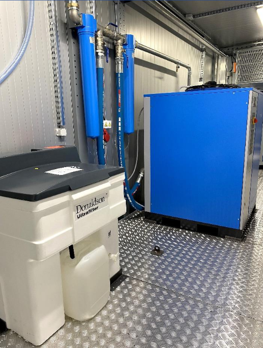
Containerized compressor stations are designed for sites requiring a compressed air or nitrogen supply where the construction of a dedicated compressor room within the facility is not feasible. Offering high mobility, these solutions enable the deployment of pneumatic systems in any location, regardless of climate conditions, while ensuring optimal operating environments and protecting internal equipment from external environmental hazards. All equipment inside the station is configured according to the client’s specific requirements. Container dimensions are tailored to the type and volume of the installed equipment, which may include compressors, nitrogen generators, boosters, receiver tanks, separators, filtration systems, and compressed air dryers. Leveraging decades of experience, our specialists have designed and manufactured hundreds of containerized stations for the compression of air, nitrogen, and even carbon dioxide.
|

|
|

|
Key Features & Benefits:
Section |
Specifications / Details |
Container dimensions (m)(LxWxH) |
10 ft: 2.438 × 2.438 × 2.991 |
20 ft: 6.058 × 2.438 × 2.991 |
40 ft: 12.192 × 2.438 × 2.991 |
|
color |
External body in RAL 7046, with any other color available upon customer request |
Internal walls: RAL 7046 or RAL 9006 |
|
Corrosion protection of the external body |
Sandblasted and painted according to corrosion category C2 to C4, depending on ambient conditions |
Floor |
Structure made of hot-rolled steel profiles + 20 mm plywood + 3 mm aluminum checker plate |
Container internal floor load capacity |
250 kg/m², meaning that over a contact area of 1000 cm², the floor can withstand a load of 2500 kg |
Internal wall panels |
Use of PWS sandwich panels with 75 mm thickness, consisting of galvanized steel sheet and fire-resistant rock wool insulation
|
Internal wall insulation |
75 mm rock wool
|
Compressed air installations |
Steel pipelines for compressed air and drainage, together with an oil drainage system including all necessary connections |
Sandblasting and painting of the steel surfaces of the above-mentioned compressed air installations carried out with high quality |
|
Electrical installations |
Galvanized cable trays protected over the entire line with proper covers |
Safety protections for each electrical device and wiring inside the container have been provided separately |
Emergency switches and emergency stop buttons for compressor operation shutdown in case of danger |
A 3P+N+PE 400V 63A switch is provided for complete power cut-off of all electrical equipment inside the container |
All electrical connections and cable parameters are suitable for the compressor’s input power and prevent compressor overload damage |
Equipped with 230V lighting protection system |
Equipped with emergency key switch |
The main switch includes a lockable rotary handle with emergency response capability |
|
Power supply |
Provided by the Employer/Customer through the main power network via the main cable entry points to the container switchboard
|
Lighting system |
| Hermetic lamps 2 × 36 W, 230 V |
| 40 ft container: 4 pcs |
| 20 ft container: 2 pcs |
| 10 ft container: 1 pcs |
|
Heating equipment |
Electric heaters 2 kW, 230 V, in metal powder-coated casing, equipped with thermostat |
40 ft container: 4 pcs |
20 ft container: 2 pcs |
10 ft container: 1 pc |
|
Ventilation system |
| Effective ventilation individually designed to provide optimal working conditions for the equipment of the container compressor station |
| Wall air intake with fixed metal shutters, filter mat, and internal gravity shutters |
| Air discharge through wall or roof louvers |
| Galvanized ventilation ducts equipped with actuator-controlled multi-blade dampers |
| Axial ventilation fan 1.1 kW or 3 kW |
| The entire ventilation system is controlled by a Siemens microprocessor controller |
|
Manufactured in accordance with standards |
2014/68/EU (PED): Pressure Equipment Directive for pressure vessels and piping systems |
2006/42/EC (MD): Machinery Directive covering machinery safety requirements |
2014/35/EU (LVD): Low Voltage Directive for electrical equipment and safety |
2014/30/EU (EMC): Electromagnetic Compatibility Directive for preventing electromagnetic interference between electrical equipment |
PN-EN ISO 12100:2012: Machinery safety – General principles for design, risk assessment, and risk reduction |
PN-EN 60204-1:2010: Safety of machinery – Electrical equipment of machines |
PN-EN 61000-6-4:2010: Electromagnetic compatibility – Emission standard for industrial environments |
PN-EN 1012-1:2011: Compressors and vacuum pumps – Safety requirements |
PN-EN 01307:1994 |
|
|
SCREW BOOSTERS | ProductID: 045
Key Features & Benefits:
Boosters are employed in industrial processes where pressure demands exceed the capability of standard plant air supply systems (typically 7-13 bar). By localized pressure boosting, these units provide the high pressure required for applications such as PET bottle production, pneumatic and hydraulic leak testing, starting large diesel engines, and spraying processes in the wood and glass industries, without requiring an increase in the entire facility’s compressed air system pressure. Airpol offers ADS series screw boosters and ADP series piston boosters for applications requiring compressed air at 40 bar. ADS screw boosters increase the inlet pressure from 7, 10, or 13 bar to 40 bar, with capacities from 250 to 500 m³/h and motor powers from 37 to 55 kW. ADP piston boosters operate as a second compression stage, raising the pressure from 8, 10, or 12 bar to 40 bar; this series has capacities from 90 to 900 m³/h and motor powers from 7.5 to 55 kW.
SCREW BOOSTERS
Model |
ProductID |
Maximum discharge pressure [bar] |
Suction pressure [bar] |
Capacity [m³/h] |
Dimensions (L × W × H)[m] |
Nominal motor power [kW] |
ADS-5 |
0450 |
max. 40 |
7 |
250 |
1.23 × 1.45 × 1.72 |
37 |
ADS-5 |
0451 |
max. 40 |
10 |
320 |
1.23 × 1.45 × 1.72 |
37 |
ADS-5 |
0452 |
max. 40 |
13 |
400 |
1.23 × 1.45 × 1.72 |
37 |
ADS-7 |
0453 |
max. 40 |
7 |
300 |
1.23 × 1.45 × 1.72 |
45 |
ADS-7 |
0454 |
max. 40 |
10 |
370 |
1.23 × 1.45 × 1.72 |
45 |
ADS-7 |
0455 |
max. 40 |
13 |
450 |
1.23 × 1.45 × 1.72 |
45 |
BS1 110 |
0456 |
max. 40 |
2097 |
1522 |
2.4 × 1.6 × 2 |
110 |
ADS-10 |
0457 |
max. 40 |
7 |
400 |
1.23 × 1.45 × 1.72 |
55 |
ADS-10 |
0458 |
max. 40 |
10 |
500 |
1.23 × 1.45 × 1.72 |
55 |
ADS-10 |
0459 |
max. 40 | >
13 |
600 |
1.23 × 1.45 × 1.72 |
55 |
PISTON BOOSTERS
Model |
ProductID |
Discharge pressure [bar] |
Suction pressure [bar] |
Capacity [m³/h] |
Nominal motor power [kW] |
ADP 7 |
04510 |
25 |
7 |
100 |
7.5 |
ADP 7 |
04511 |
25 |
10 |
140 |
7.5 |
ADP 7 |
04512 |
30 |
7 |
90 |
7.5 |
ADP 7 |
04513 |
30 |
10 |
130 |
7.5 |
ADP 15 |
04514 |
35 |
8 |
140 |
15 |
ADP 15 |
04515 |
40 |
10 |
180 |
15 |
ADP 18 |
04516 |
40 |
12 |
252 |
18.5 |
ADP 22 |
04517 |
40 |
10 |
300 |
22 |
ADP 45 |
04518 |
40 |
10 |
560 |
45 |
ADP 45 |
04519 |
40 | >
12 |
670 |
45 |
ADP 55 |
04520 |
40 | >
10 |
750 |
55 |
ADP 55 |
04521 |
40 | >
12 |
900 |
55 |
|
SCROLL COMPRESSORS | ProductID: 046
Key Features & Benefits:
Scroll compressors are the ideal solution for industries where air quality is critical, such as medical, pharmaceutical, and food sectors. Utilizing a modular design with drive motors ranging from 2.2 kW to 7.5 kW, these units produce 100% oil-free compressed air, eliminating the costs of oil filters, separators, and contaminated condensate disposal. In this range, the Airpol SR (Basic Design) series focuses on mechanical simplicity and reduced operating costs, while the SRT and SRKT (Integrated Treatment) series feature an integrated drying system. Beyond oil-free delivery, they ensure enhanced air quality (Class 1.4.0 per ISO 8573.1:2010) by maintaining a pressure dew point of +3°C, making them perfect for space-constrained environments requiring high-purity air.
SCROLL COMPRESSORS WITH COMPRESSED AIR TREATMENT
Model |
ProductID |
Capacity (m³/h) at 8 bar |
Capacity (m³/h) at 10 bar |
Dimensions (LxWxH) [m] |
Air receiver [L] |
Nominal power [kW] |
SRKT 2 (With dryer and filters) |
0460 |
15 |
12.8 |
1.44 × 0.66 × 1.25 |
240 |
2.2 |
SRKT 2 (With dryer and filters) |
0461 |
15 |
12.8 |
1.91 ×0.66 × 1.34 |
500 |
2.2 |
SRKT 4 (With dryer and filters) |
0462 |
25 |
21 |
1.44 × 0.66 × 1.25 |
240 |
3.7 |
SRKT 4 (With dryer and filters) |
0463 |
25 |
21 |
1.91 × 0.66 × 1.34 |
500 |
3.7 |
SRKT 5 (With dryer and filters) |
0464 |
36.8 |
27 |
1.91 × 0.66 × 1.34 |
500 |
5.5 |
SRKT 7 (With dryer and filters) |
0465 |
51 |
41.2 |
1.91 × 0.66 × 1.34 |
500 |
7.5 |
SRKT 2 (With dryer and filters) |
0466 |
15 |
12.8 |
0.59 × 1.00 × 1.20 |
---- |
2.2 |
SRKT 4 (With dryer and filters) |
0467 |
25 |
21 |
0.59 × 1.00 × 1.20 |
---- |
3.7 |
SRKT 5 (With dryer and filters) |
0468 |
36.8 |
27 |
0.59 × 1.00 × 1.20 |
---- |
5.5 |
SRKT 7 (With dryer and filters) |
0469 |
51 | >
41.2 |
0.59 × 1.00 × 1.20 |
---- |
7.5 |
SRKT 11 (With dryer and filters) |
04610 |
73.6 | >
54 |
1.25 × 0.62 × 1.21 |
---- |
5.5 × 2 |
SRKT 15 (With dryer and filters) |
04611 |
102 | >
82.4 |
1.25 × 0.62 × 1.21 |
---- |
7.5 × 2 |
BASIC DESIGN SCROLL COMPRESSORS
Model |
ProductID |
Capacity (m³/h) at 8 bar |
Capacity (m³/h) at 10 bar |
Dimensions (LxWxH) [m] |
Air receiver [L] |
Nominal power [kW] |
SRK 2 |
04612 |
15 |
12.8 |
1.18 × 0.59 × 1.455 |
240 |
2.2 |
SRK 2 |
04613 |
15 |
12.8 |
1.27 × 0.59 × 1.915 |
500 |
2.2 |
SRK 4 |
04614 |
25 |
21 |
1.18 × 0.59 × 1.455 |
240 |
3.7 |
SRK 4 |
04615 |
25 |
21 |
1.27 × 0.59 × 1.915 |
500 |
3.7 |
SRK 5 |
04616 |
36.8 |
27 |
1.18 × 0.59 × 1.455 |
240 |
5.5 |
SRK 5 |
04617 |
36.8 |
27 |
1.27 × 0.59 × 1.915 |
500 |
5.5 |
SRK 7 |
04618 |
51 |
41.2 |
1.27 × 0.59 × 1.915 |
500 |
7.5 |
SR 2 |
04619 |
15 |
12.8 |
1.25 × 0.9 × 0.59 |
---- |
2.2 |
SR 4 |
04620 |
25 |
21 |
1.25 × 0.9 × 0.59 |
---- |
3.7 |
SR 5 |
04621 |
36.8 | >
27 |
1.25 × 0.9 × 0.59 |
---- |
5.5 |
SR 7 |
04622 |
51 | >
41.2 |
1.25 × 0.9 × 0.59 |
---- |
7.5 |
SR 11 |
04623 |
73.6 | >
54 |
1.218 × 0.62 × 1.25 |
---- |
5.5 × 2 |
SR 15 |
04624 |
102 | >
82.4 |
1.218 × 0.62 × 1.25 |
---- |
7.5 × 2 |
SR 22 |
04625 |
147.2 | >
108 |
1.31 × 1.05 × 1.42 |
---- |
5.5 × 4 |
SR 30 |
04626 |
204 | >
165 |
1.41 × 1.15 ×1.62 |
---- |
7.5 × 4 |
SR 45 |
04627 |
306 | >
247 |
1.61 × 1.05 × 2.02 |
---- |
7.5 × 6 |
|
Mining Screw Compressors | ProductID: 047
Key Features & Benefits:
G series screw compressors are designed for compressed air supply in underground mining applications and are available in two configurations depending on the explosion hazard level of the operating environment. For mine workings outside methane explosion hazard zones, the compressors are intended primarily for non-ferrous ore mining applications. They provide compressed air up to 10 bar with capacities up to 820 m³/h and are certified by the INOVA Certification Body. These units feature fully automatic operation, overload and overtemperature protection, efficient oil separation, air cooling, and sound-insulated construction. For mine workings within methane explosion hazard zones, the compressors are designed for coal mining environments exposed to methane and coal dust explosion risks. These units comply with EU Directive 94/9/EC and are approved according to ATEX requirements by the OBAC Certification Body. Depending on the model, they provide capacities from 60 to 1110 m³/h with motor powers ranging from 11 to 110 kW, and are suitable for pneumatic equipment, compressed air systems, and spraying installations used in mining operations.
SCREW COMPRESSORS FOR MINING OPERATIONS OUTSIDE METHANE EXPLOSION HAZARD ZONE
Model |
ProductID |
Max overpressure [bar] |
Capacity [m³/h] |
Air receiver volume [L] |
Nominal electric motor power [kW] |
K7g |
0470 |
10 |
57 |
400 |
7.5 |
K11g |
0471 |
10 |
87 |
400 |
11 |
22 g |
0472 |
10 |
190 |
---- |
22 |
37 g |
0473 |
10 |
320 |
---- |
37 |
75 g |
0474 |
10 |
740 |
---- |
75 |
90 g |
0475 |
10 |
820 |
---- |
90 |
SCREW COMPRESSORS FOR MINING OPERATIONS IN METHANE EXPLOSION HAZARD ZONE
Model |
ProductID |
Max overpressure [bar] |
Capacity [m³/h] |
Dimensions (L × W × H) [m] |
Nominal electric motor power [kW] |
11 G |
0476 |
10 |
60 |
1.5 × 0.85 × 1.05 |
11 |
22 G/N |
0477 |
10 |
210 |
1.9 × 0.8 × 1 |
22 |
37 G |
0478 |
10 |
360 |
2.25 × 0.95 × 1 |
37 |
45 G/N |
0479 |
10 |
420 |
1.9 × 0.85 × 1.1 |
45 |
55 G |
04710 |
10 |
510 |
1.5 × 0.9 × 1.3 |
55 |
75 G |
04711 |
10 |
750 |
2.5 × 0.9 × 1.5 |
75 |
75 G/N |
04712 |
10 |
750 |
2.5 × 0.9 × 1.3 |
75 |
110 G |
04713 |
10 |
1100 |
2.95 × 1.2 × 1.65 |
110 |
|
Screw Compressors for the Railway Industry | ProductID:048
SK series screw compressors are designed for operation in railway rolling stock to supply compressed air for the traction vehicle pneumatic system as well as the entire train. Compressed air in railway vehicles is used not only for braking systems, but also for supplying air to a range of other pneumatic devices required for operation, such as pneumatic sirens, sand traps, current collectors, electropneumatic contactors, sanitary equipment, doors, and self-unloading wagon mechanisms. SK screw compressors are manufactured for railway applications in accordance with high quality standards to ensure a high level of safety, reliability, and operational performance. Many years of experience in designing and supplying components for traction vehicle pneumatic systems. Its offering includes both the design of new compressors and the modernization of compressors that have been used in railway rolling stock for many years.
|

|
Model |
ProductID |
Max overpressure [bar] |
Capacity [m³/h] |
Dimensions (L × W × H) [m] |
Nominal electric motor power [kW] |
Power supply [V/Ph/Hz] |
Dryer-control supply [V] |
SK 7/II T (with adsorption dryer) |
0480 |
10 |
50 |
1.74 × 0.62 × 0.7 |
9.2 |
400/3/50 |
110/24 |
SK 7/II T (with adsorption dryer) |
0481 |
10 |
50 |
1.74 × 0.62 × 0.7 |
9.2 |
400/3/50 |
24/24 |
SK 7/II |
0482 |
10 |
60 |
1.74 × 0.62 × 0.7 |
9.2 |
400/3/50 |
110/-- |
SK 7/II |
0483 |
10 |
60 |
1.74 × 0.62 × 0.7 |
9.2 |
400/3/50 |
24/-- | >
SK 11/II (with adsorption dryer) |
0484 |
10 |
66 |
1.74 × 0.62 × 0.7 |
11 |
400/3/50 |
110/24 |
SK 11/II (with adsorption dryer) |
0485 |
10 |
66 |
1.74 × 0.62 × 0.7 |
11 |
400/3/50 |
24/24 |
SK 18 |
0486 |
10 |
140 |
1.345 × 0.858 × 0.774 |
18.5 |
400/3/50 |
24/-- |
SK 30 |
0487 |
10 |
288 |
1.59 × 0.84 × 1.355 |
30 |
400/3/50 |
24/-- |
|
AIR BLOWERS | ProductID:049
Roots-type blowers are widely used in applications requiring relatively high device capacities at low compression ratios. Blowers may operate as compressors with 1 bar overpressure or as vacuum pumps with up to 0.6 bar under pressure in the capacity range from 60 to 9800 m3/h.
Blowers are primarily used in:
– aeration systems in municipal and industrial wastewater treatment plants,
– water treatment stations,
– power industry: transport of ashes,
– loose material conveying systems,
– dust extraction systems,
– food industry: drying and vacuum packaging,
– gas recirculation systems to supply air for combustion processes,
– chemical and pharmaceutical industry: for conveying and separating granulates.
Blowers are configured individually depending on the required performance and pressure parameters. Please contact our specialists to find the ideal blower for your application.
|

|
PRINCIPLE OF OPERATION:
The operation of Roots blowers is based on the cooperation of two symmetrical three-wing rotors, which rotate in opposite directions. The drive shaft on which one of the impellers is mounted drives the shaft of the other impeller through a gear transmission, so that the operation of the impellers is synchronised and contactless. When the drive shaft rotates, a defined volume of air is trapped between the casing and the impellers and passes from the suction side to the discharge side of the blower. At one full revolution of the drive shaft, the blower transports six volumes of air. While one of the volumes contained between the impellers is filled with air another is connected to a port through which the air is pushed out and compressed. The blower adapts to the counter pressure in the receiving system (installation). The volumetric flow varies only slightly with changes in system pressure, the load moment at equal pressure is constant and the capacity is proportional to the number of rotor revolutions.
|

|
|
Compressed Air Receivers | ProductID:0410
compressed air receivers are designed for the storage, pressure stabilization, and safe management of compressed air in industrial compressed air systems. Selecting an appropriately sized receiver helps reduce pressure fluctuations, cover peak demand for end-use equipment, reduce compressor start/stop frequency, and improve overall system stability. These receivers are manufactured in compliance with the Pressure Equipment Directive (PED) 2014/68/EU, with conformity assessment based on Module G. Depending on operating conditions, the vessel body is made from high-strength low-alloy steel or stainless steel, and protected with a powder coating to enhance corrosion resistance. receivers are supplied as standard in a vertical configuration; however, horizontal versions and custom specifications are also available in terms of capacity, working pressure, vessel material, medium, surface finish/coating, and colour. Each receiver is delivered with the required technical documentation and inspection certificates, ensuring traceability and compliance within quality assurance processes.
|

|
Model |
ProductID |
Air volume (L) |
Pressure [bar] |
Weight [kg] |
Connection |
Dimensions (m) |
KP-100-11 |
04100 |
100 |
11 |
61 |
G 1 |
Ø406x1.116 |
KP-100-16 |
04101 |
100 |
16 |
74 |
G 1 |
Ø406x1.116 |
KP-100-40 |
04102 |
100 |
40 |
95 |
G 1 |
ø0.406x1.14 |
KP-150-11 |
04103 |
150 |
11 |
70 |
G 1 |
ø0.457x1.14 |
KP-150-16 |
04104 |
150 |
16 |
82 |
G 1 |
ø0.457x1.35 |
KP-150-40 |
04105 |
150 |
40 |
110 |
G 1 |
ø0.457x1.4 |
KP-200-11 |
04106 |
200 |
11 |
100 |
G 5/4 |
ø0.508x1.46 |
KP-200-16 |
04107 |
200 |
16 |
130 |
G 5/4 |
ø0.508x1.46 |
KP-200-40 |
04108 |
200 |
40 |
150 |
G 5/4 |
ø0.508x1.46 |
KP-250-11 |
04109 |
250 |
11 |
106 |
G 5/4 |
ø0.508x1.755 |
KP-250-16 |
041010 |
250 |
16 |
175 |
G 5/4 |
ø0.508x1.7 |
KP-250-25 |
041011 |
250 |
25 |
185 |
G 5/4 |
ø0.612x1.33 |
KP-250-40 |
041012 |
250 |
40 |
160 |
G 5/4 |
ø0.616x1.33 |
KP-300-11 |
041013 |
300 |
11 |
115 |
G 5/4 |
ø0.608x1.45 |
KP-300-16 |
041014 |
300 |
16 |
160 |
G 5/4 |
ø0.61x1.45 |
KP-300-25 |
041015 |
300 |
25 |
180 |
G 5/4 |
ø0.612x1.45 |
KP-300-40 |
041016 |
300 |
40 |
210 |
G 5/4 |
ø0.616x1.45 |
KP-400-11 |
041017 |
400 |
11 |
170 |
G 5/4 |
ø0.608x1.79 |
KP-400-16 |
041018 |
400 |
16 |
200 |
G 5/4 |
ø0.61x1.79 |
KP-400-25 |
041019 |
400 |
25 |
240 |
G 5/4 |
ø0.612x1.79 |
KP-400-40 |
041020 |
400 |
40 |
260 |
G 5/4 |
ø0.612x1.79 |
KP-500-11 |
041021 |
500 |
11 |
190 |
G 5/4 |
ø0.6x2.12 |
KP-500-16 |
041022 |
500 |
16 |
250 |
G 5/4 |
ø0.61x2.14 |
KP-500-25 |
041023 |
500 |
25 |
260 |
G 5/4 |
ø0.612x2.14 |
KP-500-40 |
041024 |
500 |
40 |
270 |
G 5/4 |
ø0.616x2.14 |
KP-700-11 |
041025 |
700 |
11 |
225 |
G 5/4 |
ø0.91x1.15 |
KP-700-16 |
041026 |
700 |
16 |
230 |
G 5/4 |
ø0.912 x 1.51 |
KP-700-25 |
041027 |
700 |
25 |
295 |
G 5/4 |
ø0.916x1.15 |
KKP-700-40 |
041028 |
700 |
40 |
365 |
G 5/4 |
ø0.92x1.51 |
KP-900-11 |
041029 |
900 |
11 |
195 |
G 2 |
ø0.91x1.742 |
KP-1000-11 |
041030 |
1000 |
11 |
210 |
G 2 |
ø0.91x1.91 |
KP-1000-16 |
041031 |
1000 |
16 |
295 |
G 2 |
ø0.912x1.95 |
KP-1000-25 |
041032 |
1000 |
25 |
380 |
G 2 |
ø0.916x1.95 |
KP-1000-40 |
041033 |
1000 |
40 |
470 |
G 2 |
ø0.92x1.95 |
KP-1500-11 |
041034 |
1500 |
11 |
280 |
G 2 |
ø0.91x2.8 |
KP-1500-16 |
041035 |
1500 |
16 |
400 |
G 2 |
ø0.912x2.81 |
KP-1500-25 |
041036 |
1500 |
25 |
525 |
G 2 |
ø0.916x2.77 |
KP-1500-40 |
041037 |
1500 |
40 |
655 |
G 2 |
ø0.92x2.77 |
KP-2000-11/1,0 |
041038 |
2000 |
11 |
395 |
G 2 |
ø1.01 x 2.94 |
KP-2000-11 |
041039 |
2000 |
11 |
390 |
G 2 |
ø1.21 x 2.33 |
KP-2000-16 |
041040 |
2000 |
16 |
490 |
G 2 |
ø1.212x2.33 |
KP-2000-25 |
041041 |
2000 |
25 |
590 |
G 2 |
ø1.22x2.35 |
KP-2000-40 |
041042 |
2000 |
40 |
705 |
G 2 |
ø1.228x2.35 |
KP-2500-11 |
041043 |
2500 |
11 |
470 |
G 2 |
ø1.21x2.77 |
KKP-700-40 |
041044 |
700 |
40 |
365 |
G 5/4 |
ø0.92x1.51 |
KP-2500-16 |
041045 |
2500 |
16 |
610 |
G 2 |
ø1.216x2.81 |
KP-2500-25 |
041046 |
2500 |
25 |
1015 |
G 2 |
ø1.22x2.8 |
KP-2500-40 |
041047 |
2500 |
40 |
1220 |
G 2 |
ø1.228x2.8 |
KP-3000-11 |
041048 |
3000 |
11 |
535 |
G 2 |
ø0.916x1.95 |
KP-3000-16 |
041049 |
3000 |
16 |
690 |
G 2 |
ø1.216x3.3 |
KP-3000-25 |
041050 |
3000 |
25 |
1150 |
G 2 |
ø1.22x3.25 |
KP-3000-40 |
041051 |
3000 |
40 |
1380 |
G 2 |
ø1.228x3.25 |
KP-4000-9 |
041052 |
4000 |
9 |
640 |
G 3 |
ø1.41x3.15 |
KP-4000-11 |
041053 |
4000 |
11 |
780 |
G 3 |
ø1.616x2.55 |
KP-4000-12 |
041054 |
4000 |
12 |
700 |
G 3 |
ø1.412x3.16 |
KP-4000-14 |
041055 |
4000 |
14 |
1000 |
G 3 |
ø1.616x2.55 |
KP-4000-16 |
041056 |
4000 |
16 |
960 |
G 3 |
ø1.416x3.16 |
KP-4000-25 |
041057 |
4000 |
25 |
1450 |
G 3 |
ø1.424x3.2 |
KP-4000-30 |
041058 |
4000 |
30 |
1450 |
G 3 |
ø1.424x3.2 |
KP-4000-40 |
041059 |
4000 |
40 |
1700 |
G 3 |
ø1.432x3.2 |
KP-5000-9 |
041060 |
5000 |
9 |
680 |
G 3 |
ø1.41x3.83 |
KP-5000-11 |
041061 |
5000 |
11 |
930 |
G 3 |
ø1.616x3.05 |
KP-5000-12 |
041062 |
5000 |
12 |
820 |
G 3 |
ø1.412x3.83 |
KP-5000-14 |
041063 |
5000 |
14 |
1185 |
G 3 |
ø1.616x3.1 |
KP-5000-16 |
041064 |
5000 |
16 |
1090 |
G 3 |
ø1.416x3.83 |
KP-5000-25 |
041065 |
5000 |
25 |
1650 |
G 3 |
ø1.424x3.84 |
KP-5000-30 |
041066 |
5000 |
30 |
1650 |
G 3 |
ø1.424x3.84 |
KKP-5000-40 |
041067 |
5000 |
40 |
1900 |
G 3 |
ø1.428x3.86 |
KP-6000-9 |
041068 |
6000 |
9 |
900 |
G 3 |
ø2.016x2.54 |
KP-6000-11 |
041069 |
6000 |
11 |
1050 |
G 3 |
ø2.016x2.54 |
KP-6000-12 |
041070 |
6000 |
12 |
995 |
G 3 |
ø1.412 x 4.5 |
KP-6000-14 |
041071 |
6000 |
14 |
1350 |
G 3 |
ø1.616x3.4 |
KP-6000-16 |
041072 |
6000 |
16 |
1170 |
G 3 |
ø1.416x4.5 |
KP-6000-25 |
041073 |
6000 |
25 |
1950 |
G 3 |
ø1.424x4.5 |
KP-6000-30 |
041074 |
6000 |
30 |
1950 |
G 3 |
ø1.424x4.5 |
KP-8000-11 |
041075 |
8000 |
11 |
1620 |
G 3 |
ø1.616x4.55 |
KP-8000-14 |
041076 |
8000 |
14 |
1520 |
G 3 |
ø1.82x3.7 |
KP-8000-16 |
041077 |
8000 |
16 |
1485 |
G 3 |
ø2.02x3.25 |
KP-10000-8 |
041078 |
10000 |
8 |
1300 |
G 3 |
ø2.012x3.83 |
KP-10000-11/1,6 |
041079 |
10000 |
11 |
1985 |
G 3 |
ø1.612x5.69 |
KP-10000-11/1,8 |
041080 |
10000 |
11 |
1900 |
G 3 |
ø1.816x4.6 |
KP-10000-11 |
041081 |
10000 |
11 |
1830 |
G 3 |
ø2.016x3.9 |
KP-10000-14/1,8 |
041082 |
10000 |
14 |
1800 |
G 3 |
ø1.82x4.6 |
KP-10000-14 |
041083 |
10000 |
14 |
1830 |
G 3 |
ø2.02x3.9 |
KP-10000-16 |
041084 |
10000 |
16 |
1830 |
G 3 |
ø2.02x3.9 |
KP-12000-8 |
041085 |
12000 |
8 |
1500 |
G 3 |
ø2.012x4.5 |
KP-12000-11 |
041086 |
12000 |
11 |
2020 |
G 3 |
ø2.016x4.5 |
KP-12000-14 |
041087 |
12000 |
14 |
2020 |
G 3 |
ø2.02x4.5 |
KP-12000-16 |
041088 |
12000 |
16 |
2020 |
G 3 |
ø2.02x4.5 |
KP-15000-8 |
041089 |
15000 |
8 |
1750 |
G 2 |
ø2.012x5.4 |
KP-15000-11 |
041090 |
15000 |
11 |
2385 |
G 2 |
ø2.016x5.4 |
KP-15000-11/2,2 |
041091 |
15000 |
11 |
2500 |
G 2 |
ø2.216x4.645 |
KP-15000-14 |
041092 |
15000 |
14 |
2385 |
G 2 |
ø2.02x5.4 |
KP-15000-16 |
041093 |
15000 |
16 |
2385 |
G 2 |
ø2.02 x 5.4 |
KP-20000-10 |
041094 |
20000 |
10 |
2900 |
G 2 |
ø2.216x5.98 |
KP-20000-10 |
041084 |
20000 |
10 |
2710 |
G 2 |
ø2.416x5.1 |
KP-20000-11 |
041095 |
20000 |
11 |
2710 |
G 2 |
ø2.416x5.1 |
KP-20000-14 |
041096 |
20000 |
14 |
3400 |
G 2 |
ø2.42x5.1 |
KP-25000-10 |
041084 |
25000 |
10 |
3500 |
G 2 |
ø2.216x7.33 |
KP-25000-10 |
041097 |
25000 |
10 |
3250 |
G 2 |
ø2.416x6.18 |
KP-25000-11 |
041084 |
25000 |
11 |
3300 |
G 2 |
ø2.416x6.18 |
KP-25000-14 |
041098 |
25000 |
14 |
4065 |
G 2 |
ø2.42x6.187 |
KP-30000-10 |
041099 |
30000 |
10 |
4075 |
G 2 |
ø2.216x8.63 |
KP-30000-10 |
0410100 |
30000 |
10 |
3770 |
G 2 |
ø2.416x7.28 |
KP-30000-11 |
0410101 |
30000 |
11 |
3835 |
G 2 |
ø2.416x7.28 |
KP-30000-14 |
0410102 |
30000 |
14 |
4735 |
G 2 |
ø2.42x7.29 |
KP-10000-16 |
0410103 |
10000 |
16 |
1830 |
G 3 |
ø2.02x3.9 |
|
Compressed air drying - Refrigeration air dryers | ProductID:0411
The refrigeration air dryer is an ideal component of a pneumatic installation which removes water and water vapor from compressed air and ensures drying at the pressure dew point temperature of +3ºC. The pressure dew point defines the temperature to which compressed air can be cooled without condensation of the contained water. The atmospheric air sucked in by the compressor contains water vapor and solid impurities. After compression, the exhaust air has a temperature about 10 degrees higher than the ambient temperature (screw compressor). As a result of the contact with ambient conditions and the resulting temperature difference, the air cools and condensate are precipitated from it, which can cause corrosion, accelerate wear and tear on pipelines and installed equipment and tools, and thus disrupt the production process. A perfect solution that can minimize the risk of these adverse effects is the use of a refrigeration air dryer together with compressed air filters. They allow to obtain air dried and free from impurities.
|

|
Model |
ProductID |
Air flow [m³/h] |
Dryer pressure dew point [°C] |
Max working pressure [bar] |
Dimensions (L×W×H) [m] |
OPA 10 |
04110 |
50 |
+3 |
16 |
0.372 × 0.404 × 0.38 |
OPA 20 |
04111 |
72 |
+3 |
16 |
0.372 × 0.404 × 0.38 |
OPA 30 |
04112 |
110 |
+3 |
16 |
0.372 × 0.424× 0.446 |
OPA 40 |
04113 |
140 |
+3 |
16 |
0.46 × 0.44 × 0.5 |
OPA 50 |
04114 |
180 |
+3 |
16 |
0.52 × 0.54 × 0.55 |
OPA 60 |
04115 |
216 |
+3 |
16 |
0.47 × 0.51 × 0.81 |
OP 65 |
04116 |
246 |
+3 |
14 |
0.46 × 575 × 0.79 |
OP 70 |
04117 |
312 |
+3 |
14 |
0.46 × 0.575 × 0.79 |
OP 80 |
04118 |
390 |
+3 |
14 |
0.58 × 0.587 × 0.9 |
OP 90 |
04119 |
462 |
+3 |
14 |
0.58 × 0.587 × 0.9 |
OP 100 |
041110 |
600 |
+3 |
14 |
0.805 × 1.07 × 0.962 |
OP 110 |
041111 |
720 |
+3 |
14 |
0.805 × 1.07 × 0.962 |
OP 120 |
041112 |
900 |
+3 |
14 |
0.805 × 1.07 × 0.962 |
OP 130 |
041113 |
1080 |
+3 |
14 |
0.805 × 1.07 × 0.962 |
OP 140 |
041114 |
1440 |
+3 |
14 |
1.132 × 1.005 × 1.399 |
OP 150 |
041115 |
1800 |
+3 |
14 |
1.271 × 1.005 × 1.596 |
OP 160 |
041116 |
2100 |
+3 |
14 |
1.271 × 1.005 × 1.596 |
OP 170 |
041117 |
3000 |
+3 |
14 |
1.652 × 1.005 × 1.826 |
OP 180 |
041118 |
4200 |
+3 |
14 |
1.652 × 1.005 × 1.826 |
OP 190 |
041119 |
5040 |
+3 |
14 |
1.979 × 1.455 × 1.826 |
|
Compressed air drying - Cold Regenerated Adsportion Dryears | productID: 0412
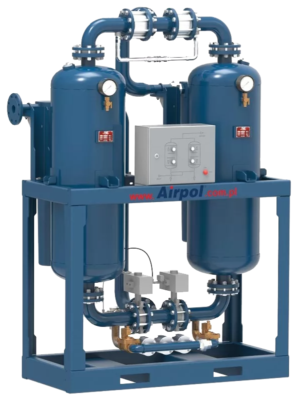
Adsorption dryers are used in cases where compressed air systems are exposed to freezing or where very dry air is required in specific applications; for example, process air in the electronics, chemical, food and pharmaceutical industries or instrumentation air. The purpose of using this equipment is to separate moisture from the compressed air stream and achieve the desired degree of dryness based on the pressure dew point temperature. Designed cold regenerated adsorption dryers guarantee achieving the highest quality of compressed air with a super dry dew point up to -70°C in the standard version. In addition, the installed compressed air filters (on the device), which are an integral part of adsorption dryers, guarantee complete purification of the air from solid particles and oil mist. By treating compressed air with adsorption dryers, it can be ensured that the compressed air used will be a completely stable, safe and contamination-free medium.
|
|
Model |
ProductID |
Air flow [m3/h] |
Dryer pressure dew point [°C] |
Quality class in accordance with ISO 8573.1 |
Max working pressure [bar] |
Dimensions (LxWxH) [m] |
NDA 0005/NDA 0005 SP |
04120 |
5 |
+20 |
1.3.1 |
10 |
0.72 × 0.5 × 0.92 |
NDA 0010/NDA 0010 SP |
04121 |
10 |
+20 |
1.3.1 |
10 |
0.72 × 0.5 × 0.92 |
NDA 0015/NDA 0015 SP |
04122 |
15 |
+20 |
1.3.1 |
10 |
0.72 × 0.5 × 0.92 |
NDA 0025/NDA 0025 SP |
04123 |
25 |
+20 |
1.3.1 |
10 |
0.72 × 0.54 × 1.34 |
NDA 0035/NDA 0035 SP |
04124 |
35 |
+20 |
1.3.1 |
10 |
0.72 × 0.54 × 1.34 |
NDA 0050/NDA 0050 SP |
04125 |
50 |
+20 |
1.3.1 |
10 |
0.72 × 0.55 × 1.39 |
NDA 0080/NDA 0080 SP |
04126 |
80 |
+20 |
1.3.1 |
10 |
0.72 × 0.55 × 1.39 |
NDA 0100/NDA 0100 SP |
04127 |
100 |
+20 |
1.3.1 |
10 |
0.85 × 0.59 × 1.5 |
NDA 0150/NDA 0150 SP |
04128 |
150 |
+20 |
1.3.1 |
10 |
0.85 × 0.66 × 1.82 |
NDA 0175/NDA 0175 SP |
04129 |
175 |
+20 |
1.3.1 |
10 |
0.85 × 0.66 × 1.82 |
NDA 0225/NDA 0225 SP |
041210 |
225 |
+20 |
1.3.1 |
10 |
0.85 × 0.66 × 1.82 |
NDA 0300/NDA 0300 SP |
041211 |
300 |
+20 |
1.3.1 |
10 |
1 × 0.7 × 1.72 |
NDA 0375/NDA 0375 SP |
041213 |
375 |
+20 |
1.3.1 |
10 |
1 × 0.7 × 1.72 |
NDA 0550/NDA 0550 SP |
041214 |
550 |
+20 |
1.3.1 |
10 |
1.15 × 0.78 × 1.81 |
NDA 0650/NDA 0650 SP |
041215 |
650 |
+20 |
1.3.1 |
10 |
1.15 × 0.78 × 1.81 |
NDA 0850/NDA 0850 SP |
041216 |
850 |
+20 |
1.3.1 |
10 |
1.25 × 0.735 × 2.13 |
NDA 1000/NDA 1000 SP |
041217 |
1000 |
+20 |
1.3.1 |
10 |
1.25 × 0.735 × 2.13 |
NDA 1350/NDA 1350 SP |
041218 |
1350 |
+20 |
1.3.1 |
10 |
1.92 × 0.915 × 2.28 |
NDA 1650/NDA 1650 SP |
041219 |
1650 |
+20 |
1.3.1 |
10 |
1.8 × 1.12 × 2.17 |
NDA 1950/NDA 1950 SP |
041220 |
1950 |
+20 |
1.3.1 |
10 |
1.8 × 1.12 × 2.17 |
NDA 2250/NDA 2250 SP |
041221 |
2250 |
+20 |
1.3.1 |
10 |
1.9 × 1.29 × 2.6 |
NDA 2750/NDA 2750 SP |
041222 |
2750 |
+20 |
1.3.1 |
10 |
2.2 × 1.5 × 2.7 |
NDA 3500/NDA 3500 SP |
041223 |
3500 |
+20 |
1.3.1 |
10 |
2.2 × 1.5 × 2.7 |
NDA 4000/NDA 4000 SP |
041224 |
4000 |
+20 |
1.3.1 |
10 |
2.45 × 1.65 × 3 |
OAD 0005/OAD 0005 SP |
041225 |
5 |
+40 |
1.2.1 |
10 |
0.72 × 0.5 × 0.92 |
OAD 0010/OAD 0010 SP |
041226 |
10 |
+40 |
1.2.1 |
10 |
0.72 × 0.5 × 0.92 |
OAD 0015/OAD 0015 SP |
041227 |
15 |
+40 |
1.2.1 |
10 |
0.72 × 0.5 × 0.92 |
OAD 0025/OAD 0025 SP |
041228 |
25 |
+40 |
1.2.1 |
10 |
1.34 × 0.54 × 0.72 |
OAD 0035/OAD 0035 SP |
041229 |
35 |
+40 |
1.2.1 |
10 |
1.34 × 0.54 × 0.72 |
OAD 0050/OAD 0050 SP |
041230 |
50 |
+40 |
1.2.1 |
10 |
1.39 × 0.55 × 0.72 |
OAD 0080/OAD 0080 SP |
041231 |
80 |
+40 |
1.2.1 |
10 |
1.39 × 0.55 × 0.72 |
OAD 0100/OAD 0100 SP |
041232 |
100 |
+40 |
1.2.1 |
10 |
0.85 × 0.59 × 1.5 |
OAD 0150/OAD 0150 SP |
041233 |
150 |
+40 |
1.2.1 |
10 |
0.85 × 0.59 × 1.5 |
OAD 0175/OAD 0175 SP |
041234 |
175 |
+40 |
1.2.1 |
10 |
1.82 × 0.66 × 0.85 |
OAD 0225/OAD 0225 SP |
041235 |
225 |
+40 |
1.2.1 |
10 |
1.82 × 0.66 × 0.85 |
OAD 0300/OAD 0300 SP |
041236 |
300 |
+40 |
1.2.1 |
10 |
1 × 0.7 × 1.72 |
OAD 0375/OAD 0375 SP |
041237 |
375 |
+40 |
1.2.1 |
10 |
1 × 0.7 × 1.72 |
OAD 0550/OAD 0550 SP |
041238 |
550 |
+40 |
1.2.1 |
10 |
1.15 × 0.78 × 1.81 |
OAD 0650/OAD 0650 SP |
041239 |
650 |
+40 |
1.2.1 |
10 |
1.15 × 0.78 × 1.81 |
OAD 0850/OAD 0850 SP |
041240 |
850 |
+40 |
1.2.1 |
10 |
1.25 × 0.735 × 2.13 |
OAD 1000/OAD 1000 SP |
041241 |
1000 |
+40 |
1.2.1 |
10 |
1.25 × 0.735 × 2.13 |
OAD 1350/OAD 1350 SP |
041242 |
1350 |
+40 |
1.2.1 |
10 |
1.92 × 0.915 × 2.28 |
OAD 1650/OAD 1650 SP |
041243 |
1650 |
+40 |
1.2.1 |
10 |
1.8 × 1.12 × 2.17 |
OAD 1950/OAD 1950 SP |
041244 |
1950 |
+40 |
1.2.1 |
10 |
1.8 × 1.12 × 2.17 |
OAD 2250/OAD 2250 SP |
041245 |
2250 |
+40 |
1.2.1 |
10 |
1.9 × 1.29 × 2.6 |
OAD 2750/OAD 2750 SP |
041246 |
2750 |
+40 |
1.2.1 |
10 |
2.2 × 1.5 × 2.7 |
OAD 3500/OAD 3500 SP |
041247 |
3500 |
+40 |
1.2.1 |
10 |
2.2 × 1.5 × 2.7 |
OAD 4000/OAD 4000 SP |
041248 |
4000 |
20- |
1.3.1 |
10 |
2.45 × 1.65 × 3 |
ADU 0005/ADU 0005 SP |
041249 |
5 |
-70 |
1.1.1 |
10 |
0.92 × 0.5 × 0.72 |
ADU 0010/ADU 0010 SP |
041250 |
10 |
-70 |
1.1.1 |
10 |
0.92 × 0.5 × 0.72 |
ADU 0015/ADU 0015 SP |
041251 |
15 |
-70 |
1.1.1 |
10 |
0.92 × 0.5 × 0.72 |
ADU 0025/ADU 0025 SP |
041252 |
25 |
-70 |
1.1.1 |
10 |
1.34 × 0.54 × 0.72 |
ADU 0035/ADU 0035 SP |
041253 |
35 |
-70 |
1.1.1 |
10 |
1.34 × 0.54 × 0.72 |
ADU 0050/ADU 0050 SP |
041254 |
50 |
-70 |
1.1.1 |
10 |
1.39 × 0.55 × 0.72 |
ADU 0080/ADU 0080 SP |
041255 |
80 |
-70 |
1.1.1 |
10 |
1.39 × 0.55 × 0.72 |
ADU 0100/ADU 0100 SP |
041256 |
100 |
-70 |
1.1.1 |
10 |
0.85 × 0.59 × 1.5 |
ADU 0150/ADU 0150 SP |
041257 |
150 |
-70 |
1.1.1 |
10 |
1.82 × 0.66 × 0.85 |
ADU 0175/ADU 0175 SP |
041258 |
175 |
-70 |
1.1.1 |
10 |
1.82 × 0.66 × 0.85 |
ADU 0225/ADU 0225 SP |
041259 |
225 |
-70 |
1.1.1 |
10 |
1.82 × 0.66 × 0.85 |
ADU 0300/ADU 0300 SP |
041260 |
300 |
-70 |
1.1.1 |
10 |
1 × 0.7 × 1.72 |
ADU 0375/ADU 0375 SP |
041261 |
375 |
-70 |
1.1.1 |
10 |
1 × 0.7 × 1.72 |
ADU 0550/ADU 0550 SP |
041262 |
550 |
-70 |
1.1.1 |
10 |
1.15 × 0.78 × 1.81 |
ADU 0650/ADU 0650 SP |
041263 |
650 |
-70 |
1.1.1 |
10 |
1.15 × 0.78 × 1.81 |
ADU 0850/ADU 0850 SP |
041264 |
850 |
-70 |
1.1.1 |
10 |
1.25 × 0.735 × 2.13 |
ADU 1000/ADU 1000 SP |
041265 |
1000 |
-70 |
1.1.1 |
10 |
1.25 × 0.735 × 2.13 |
ADU 1350/ADU 1350 SP |
041266 |
1350 |
-70 |
1.1.1 |
10 |
1.92 × 0.915 × 2.28 |
ADU 1650/ADU 1650 SP |
041267 |
1650 |
-70 |
1.1.1 |
10 |
1.8 × 1.12 × 2.17 |
ADU 1950/ADU 1950 SP |
041268 |
1950 |
-70 |
1.1.1 |
10 |
1.8 × 1.12 × 2.17 |
ADU 2250/ADU 2250 SP |
041269 |
2250 |
-70 |
1.1.1 |
10 |
1.9 × 1.29 × 2.6 |
ADU 2750/ADU 2750 SP |
041270 |
2750 |
-70 |
1.1.1 |
10 |
2.2 × 1.5 × 2.7 |
ADU 3500/ADU 3500 SP |
041271 |
3500 |
-70 |
1.1.1 |
10 |
2.2 × 1.5 × 2.7 |
ADU 4000/ADU 4000 SP |
041271 |
4000 |
-70 |
1.1.1 |
10 |
2.45 × 1.65 × 3 |
|
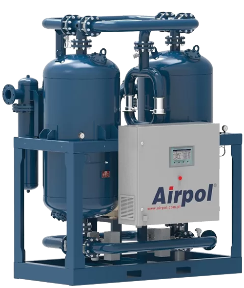
Compressed air drying – Heat Regenerated Adsorption Dryers | ProductID: 0413
SGR series heat regenerated adsorption dryers are specially designed for applications where very high flow rates and volumes of dried compressed air are required. The function of these units is to separate moisture from compressed air in order to achieve the required degree of dryness, expressed by the pressure dew point temperature. SGR series heat regenerated adsorption dryers, in their standard version, are capable of supplying high-quality compressed air with a pressure dew point of -40°C. In the case of more stringent quality requirements, these dryers can also be manufactured in special versions to improve the system pressure dew point to -70°C at high flow rates. The distinguishing feature in selecting these units is that, in SGR dryers, the regeneration and moisture removal of the adsorbent material inside the towers are carried out by blowing heated ambient air through the beds; this engineering innovation allows the losses and waste of compressed air in the system to be minimized.
|
|
Model |
ProductID |
Air flow [m3/h] |
Dryer pressure dew point [°C] |
Quality class in accordance with ISO 8573.1 |
Max working pressure [bar] |
Dimensions (LxWxH) [m] |
SGR 0300 |
04130 |
300 |
-40 |
1.2.1 |
10 |
1.2 × 1.44 × 2.19 |
SGR 0375 |
04131 |
375 |
-40 |
1.2.1 |
10 |
1.2 × 1.44 × 2.19 |
SGR 0550 |
04132 |
550 |
-40 |
1.2.1 |
10 |
1.35 × 1.26 × 2.29 |
SGR 0650 |
04133 |
650 |
-40 |
1.2.1 |
10 |
1.35 × 1.26 × 2.29 |
SGR 0850 |
04134 |
850 |
-40 |
1.2.1 |
10 |
1.6 × 1.35 × 2.2 |
SGR 1000 |
04135 |
1000 |
-40 |
1.2.1 |
10 |
1.6 × 1.35 × 2.2 |
NDA 0080/NDA 0080 SP |
04136 |
80 |
-20 |
1.3.1 |
10 |
0.72 × 0.55 × 1.39 |
SGR 1350 |
04137 |
1350 |
-40 |
1.2.1 |
10 |
1.9 × 1.59 × 2.3 |
NDA 0150/NDA 0150 SP |
04138 |
150 |
-20 |
1.3.1 |
10 |
0.85 × 0.66 × 1.82 |
SGR 1650 |
04139 |
1650 |
-40 |
1.2.1 |
10 |
1.9 × 1.59 × 2.3 |
SGR 1950 |
041310 |
1950 |
-40 |
1.2.1 |
10 |
2.25 × 1.66 × 2.69 |
SGR 2250 |
041311 |
2250 |
-40 |
1.2.1 |
10 |
2.25 × 1.66 × 2.69 |
SGR 2750 |
041311 |
2750 |
-40 |
1.2.1 |
10 |
2.25 × 1.87 × 2.87 |
SGR 3500 |
041311 |
3500 |
-40 |
1.2.1 |
10 |
3 × 2.2 × 3.2 |
SGR 4000 |
041311 |
4000 |
-40 |
1.2.1 |
10 |
3 × 2.2 × 3.2 |
|
Compressed Air Drying - Medical Air Dryers | ProductID: 0414
Ultrapure Smart dryers are designed based on adsorption technology, and their function is to remove moisture from compressed air. These units supply compressed, clean, and dry breathing air in compliance with the standards and requirements defined for medical applications. Ultrapure Smart dryers are offered as complete air treatment packages and include an adsorption dryer, a CO, CO2, NOx, and SO2 scavenger, a pre-filter, a post-filter, and an automatic condensate drain. Despite being complete units, they have a compact and space-saving design. The adsorbent material is placed inside replaceable cartridges. In addition, a special indicator informs the user when the cartridges and filter elements should be replaced. This timing is determined by the manufacturer in such a way that device operating safety and the required air quality are maintained throughout the entire service life. Ultrapure Smart dryers are available in two versions: Standard and Super-plus. The Super-plus models are additionally equipped with an automatic diagnostic system that operates based on monitoring regenerated air flow parameters through sensors. These models also feature load-dependent control, meaning that the operating cycle of the unit is automatically adjusted according to the moisture level of the inlet air. This feature results in regeneration air savings and lower operating costs.
|

|
Model |
ProductID |
Air flow [m3/h] |
Dryer pressure dew point [°C] |
Max working pressure [bar] |
Dimensions (LxWxH) [m] |
Ultrapure Smart 0005 Standard |
04140 |
5 |
-40 |
14 |
0.314 × 0.172 × 0.49 |
Ultrapure Smart 0005 Superplus |
04141 |
5 |
-40 |
14 |
0.3147 × 0.191 × 0.49 |
Ultrapure Smart 0010 Standard |
04142 |
10 |
-40 |
14 |
0.314 × 0.172 × 0.757 |
Ultrapure Smart 0010 Superplus |
04143 |
10 |
-40 |
14 |
0.314 × 0.191 × 0.764 |
Ultrapure Smart 0015 Standard |
04144 |
15 |
-40 |
14 |
0.314 × 0.172 × 1.024 |
Ultrapure Smart 0015 Superplus |
04145 |
15 |
-40 |
14 |
0.314 × 0.191 × 1.031 |
Ultrapure Smart 0020 Standard |
04146 |
20 |
-40 |
14 |
0.314 × 0.172 × 1.291 |
Ultrapure Smart 0020 Superplus |
04147 |
20 |
-40 |
14 |
0.314 × 0.191 × 1.298 |
Ultrapure Smart 0025 Standard |
04148 |
25 |
-40 |
14 |
0.314 × 0.172 × 1.558 |
Ultrapure Smart 0025 Superplus |
04149 |
25 |
-40 |
14 |
0.314 × 0.191 × 1.565 |
Ultrapure Smart 0035 Standard |
041410 |
35 |
-40 |
12 |
0.464 × 0.276 × 0.849 |
Ultrapure Smart 0035 Superplus |
041411 |
35 |
-40 |
12 |
0.464 × 0.291 × 0.866 |
Ultrapure Smart 0050 Standard |
041412 |
50 |
-40 |
12 |
0.464 × 0.276 × 1.113 |
Ultrapure Smart 0050 Superplus |
041413 |
50 |
-40 |
12 |
0.464 × 0.291 × 1.130 |
Ultrapure Smart 0065 Standard |
041414 |
65 |
-40 |
12 |
0.464 × 0.276 × 1.377 |
Ultrapure Smart 0065 Superplus |
041415 |
65 |
-40 |
12 |
0.464 × 0.291 × 1.394 |
Ultrapure Smart 0080 Standard |
041416 |
80 |
-40 |
12 |
0.464 × 0.276 × 1.641 |
Ultrapure Smart 0080 Superplus |
041417 |
80 |
-40 |
12 |
0.464 × 0.291 × 1.658 |
Ultrapure Smart 0100 Standard |
041418 |
100 |
-40 |
12 |
0.464 × 0.276 × 1.905 |
Ultrapure Smart 0100 Superplus |
041419 |
100 |
-40 |
12 |
0.464 × 0.291 × 1.922 |
|
Compressed Air Drying – Refrigertion Air Dryers (40 Bar) | ProductID: 0415
OP HP high-pressure units are used for drying air compressed to a pressure of max 45 bar. They belong to the group of refrigerated air dryers in which the incoming compressed air is initially cooled in a heat exchanger (air-air) and then flows through a heat exchanger (refrigerant-air), where it is further cooled to the required pressure dew point of +3ºC. Moisture from the compressed air is condensed and removed automatically via an electronic condensate drain. In the final stage, the cold air is reheated by the compressed air entering the dryer. This technology saves energy and protects the compressed air system against moisture condensation upstream of the dryer. Condensate precipitated from the compressed air could cause corrosion and accelerate the wear of pipelines and installed equipment, thereby disrupting the production process. The use of an OP HP refrigerated air dryer will help to prevent these adverse effects and save the user from additional costs.
|
|
Model |
ProductID |
Air flow (m³/h) |
Dryer pressure dew point (°C) |
Max. working pressure (bar) |
Dimensions (L×W×H) (m) |
OP 100 HP |
04150 |
100 |
+3 |
45 |
0.499 × 0.485 × 0.352 |
OP 140 HP |
04151 |
140 |
+3 |
45 |
0.684 × 0.552 × 0.356 |
OP 180 HP |
04152 |
180 |
+3 |
45 |
0.684 × 0.552 × 0.356 |
OP 235 HP |
04153 |
235 |
+3 |
45 |
0.684 × 0.552 × 0.356 |
OP 300 HP |
04154 |
300 |
+3 |
45 |
0.684 × 0.552 × 0.356 |
OP 380 HP |
04155 |
380 |
+3 |
45 |
0.684 × 0.552 × 0.356 |
OP 480 HP |
04156 |
480 |
+3 |
45 |
0.827 × 0.589 × 0.495 |
OP 600 HP |
04157 |
600 |
+3 |
45 |
0.827 × 0.589 × 0.495 |
OP 750 HP |
04158 |
750 |
+3 |
45 |
0.973 × 0.708 × 0.491 |
OP 950 HP |
04159 |
950 |
+3 |
45 |
0.973 × 0.708 × 0.491 |
OP 1500 HP |
041510 |
1500 |
+3 |
45 |
1.047 × 1.337 × 0.72 |
OP 1900 HP |
041511 |
1900 |
+3 |
45 |
1.047 × 1.337 × 0.72 |
OP 2250 HP |
041512 |
2250 |
+3 |
45 |
1.187 × 1.394 × 0.855 |
OP 2850 HP |
041513 |
2850 |
+3 |
45 |
1.187 × 1.394 × 0.855 |
OP 3800 HP |
041514 |
3800 |
+3 |
45 |
1.493 × 1.493 × 1.162 |
OP 4750 HP |
041515 |
4750 |
+3 |
45 |
1.237 × 1.544 × 1.268 |
|
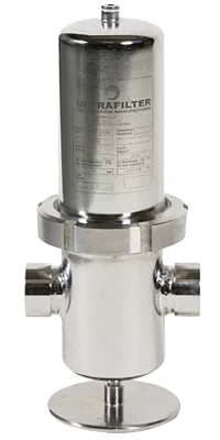
Compressed air filtering | ProductID: 0416
Models:
1) COMPRESSED AIR FILTERS (16 BAR)
2) COMPRESSED AIR FILTERS (40 BAR)
3) STERILE FILTERS
4) CYCLONE SEPARATORS
|
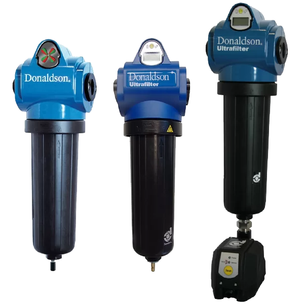
COMPRESSED AIR FILTERS (16 BAR)
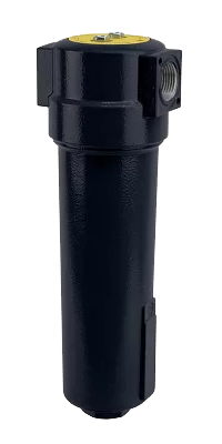
Compressed air filters are an indispensable element of the air treatment system whose task is to improve air quality by removing particulate matter and oil. Care for proper treatment of compressed air increases the reliability of machines and the entire process. Consequently, proper compressed air treatment is essential to reduce equipment downtime and to cut maintenance and energy costs. Proper selection of compressed air filters is a compilation of three key factors: desired air purity, required flow rate and air pressure.
|
|
Model |
ProductID |
Air flow (m³/h) |
Dryer pressure dew point (°C) |
Max. working pressure (bar) |
Connection |
Cartridge |
BFP 78 |
04160 |
78 |
1.3 |
16 |
½G |
Q, P, S, C |
FP 120 |
04161 |
120 |
2 |
16 |
¾G |
Q, P, S, C |
FP 335 |
04162 |
335 |
5.6 |
16 |
G1 |
Q, P, S, C |
FP 510 |
04163 |
510 |
8.5 |
16 |
½G1 |
Q, P, S, C |
FP 780 |
04164 |
780 |
13 |
16 |
½G1 |
Q, P, S, C |
FP 996 |
04165 |
1000 |
16.6 |
16 |
G2 |
Q, P, S, C |
FP 1500 |
04166 |
1500 |
25 |
16 |
G2 |
Q, P, S, C |
FP 2400 |
2760 |
40 |
16 |
16 |
G3 |
Q, P, S, C |
FP 1680 |
04168 |
1680 |
28 |
16 |
DN 80 |
Q, P, S, C |
FP 3150 |
04169 |
3150 |
52.5 |
16 |
DN 100 |
Q, P, S, C |
FP 4700 |
041610 |
4700 |
78.3 |
16 |
DN 125 |
Q, P, S, C |
FP 6300 |
041611 |
6300 |
105 |
16 |
DN 150 |
Q, P, S, C |
FP 9400 |
041612 |
9400 |
156.7 |
16 |
DN 150 |
Q, P, S, C |
FP 12550 |
041613 |
12550 |
209.2 |
16 |
DN 200 |
Q, P, S, C |
DF 0035 ST/SP |
041614 |
35 |
0.58 |
16 |
½G |
V, M, S, A |
DF 0070 ST/SP |
041615 |
70 |
1.17 |
16 |
⅜G |
V, M, S, A |
DF 0120 ST/SP |
041616 |
120 |
2 |
16 |
½G |
V, M, S, A |
DF 0210 ST/SP |
041617 |
210 |
3.5 |
16 |
¾G |
V, M, S, A |
DF 0320 ST/SP |
041618 |
320 |
5.33 |
16 |
G1 |
V, M, S, A |
DF 0450 ST/SP |
041619 |
450 |
7.5 |
16 |
¼G1 |
V, M, S, A |
DF 0600 ST/SP |
041620 |
600 |
10 |
16 |
½G1 |
V, M, S, A |
DF 0750 ST/SP |
041621 |
750 |
12.5 |
16 |
G2 |
V, M, S, A |
DF 1100 ST/SP |
041622 |
1100 |
18.33 |
16 |
G2 |
V, M, S, A |
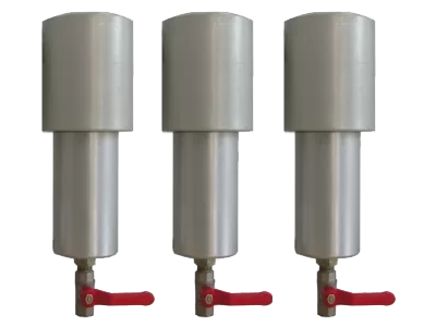
COMPRESSED AIR FILTERS (40 BAR)
HP series compressed air filters are used as part of compressed air treatment systems up to 40 bar. Their purpose is to improve air quality by removing solid particles and oil. Care for proper treatment of compressed air increases the reliability of machines and the entire process. Consequently, proper compressed air treatment is essential to reduce equipment downtime and to cut maintenance and energy costs. Proper selection of compressed air filters is a compilation of three key factors: desired air purity, required flow rate and air pressure.
|
|
Model |
ProductID |
Air flow (m³/h) |
Dryer pressure dew point (°C) |
Max. working pressure (bar) |
Connection |
Cartridge |
HP 500 MF |
041623 |
500 |
8.3 |
40 |
3.4 |
05/20 MF |
HP 500 SMF |
041624 |
500 |
8.3 |
40 |
3.4 |
05/20 MF |
HP 500 AK |
041625 |
500 |
8.3 |
40 |
3.4 |
05/20 AK |
HP 900 MF |
041626 |
900 |
15 |
40 |
5.4 |
05/25 MF |
HP 900 SMF |
041627 |
900 |
15 |
40 |
5.4 |
05/25 SMF |
HP 900 AK |
041628 |
900 |
15 |
40 |
5.4 |
05/25 AK |
STERILE FILTERS
Model |
ProductID |
Air flow [m³/h] |
Air flow [m³/min] |
Max pressure [bar] |
Connection |
Cartridge |
P-SRF N 0006 |
041629 |
60 |
1 |
16 |
G1/4 |
03/10 |
P-SRF N 0009 |
041630 |
90 |
1.5 |
16 |
G3/8 |
04/10 |
P-SRF N 0012 |
041631 |
120 |
2 |
16 |
G1/2 |
04/20 |
P-SRF N 0018 |
041632 |
180 |
3 |
16 |
G3/4 |
05/20 |
P-SRF N 0027 |
041633 |
270 |
4.5 |
16 |
G1 |
05/25 |
P-SRF N 0036 |
041634 |
360 |
6 |
16 |
G1 1/4 |
07/25 |
P-SRF N 0048 |
041635 |
480 |
8 |
16 |
G1 1/2 |
07/30 |
P-SRF N 0072 |
041636 |
720 |
12 |
16 |
G2 |
10/30 |
P-SRF N 0108 |
041637 |
1,080 |
18 |
16 |
G2 |
15/30 |
P-SRF N 0144 |
041638 |
1440 |
24 |
16 |
G2 1/2 |
20/30 |
P-SRF N 0192 |
041639 |
1920 |
32 |
16 |
G3 |
30/30 |
CYCLONE SEPARATORS
Model |
ProductID |
Air flow [m³/min] |
Max working pressure [bar] |
Working temperature [°C] |
Compressed air connection |
Weight (kg) |
ASC 001 |
041640 |
2 |
16 |
65+÷1+ |
⅜G |
0.7 |
ASC 002 |
041641 |
2.6 |
16 |
65+÷1+ |
½G |
0.7 |
ASC 003 |
041642 |
3.9 |
16 |
65+÷1+ |
¾G |
0.8 |
ASC 004 |
041643 |
6 |
16 |
65+÷1+ |
G1 |
1.8 |
ASC 005 |
041644 |
13 |
16 |
65+÷1+ |
½G1 |
2.5 |
ASC 006 |
041645 |
21 |
16 |
65+÷1+ |
G2 |
5.1 |
ASC 007 |
041646 |
41 |
16 |
65+÷1+ |
½G2 |
12.9 |
ASC 008 |
041647 |
48 |
16 |
65+÷1+ |
G3 |
1.6 |
DF-C 0120 ST/SP |
041648 |
2 |
16 |
65+÷1+ |
½G |
1.6 |
DF-C 0210 ST/SP |
041649 |
3.5 |
16 |
65+÷1+ |
¾G |
2.7 |
DF-C 0320 ST/SP |
041650 |
5.3 |
16 |
65+÷1+ |
G1 |
2.7 |
DF-C 0450 ST/SP |
041651 |
7.5 |
16 |
65+÷1+ |
½G1 |
2.9 |
DF-C 0750 ST/SP |
041652 |
12.5 |
16 |
65+÷1+ |
G2 |
2.9 |
DF-C 1100 ST/SP |
041653 |
18.3 |
16 |
65+÷1+ |
G2 |
2.9 |
|
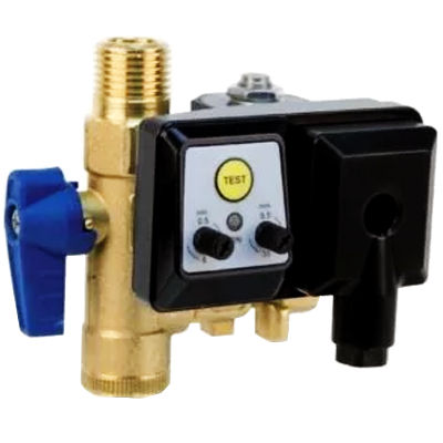
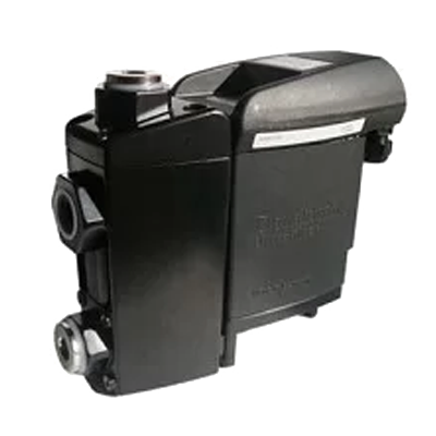
Drains | ProductID: 0417
Models:
1) OIL/WATER SEPARATORS
2) CONDENSATE DRAINS
|
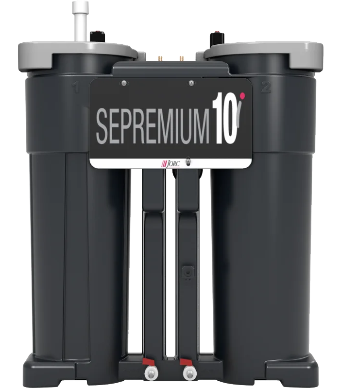
OIL/WATER SEPARATORS
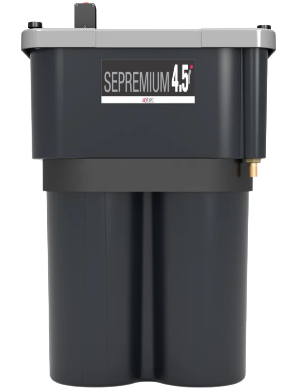
SEPREMIUM oil/water separators are used to treat compressed air condensate. Their function is to separate the compressor oil from the condensate, thus enabling the remaining water (treated in an activated carbon bed) to be discharged directly into the sewerage system. The use of a separator is not only environmentally friendly, but also a major improvement in the disposal of compressed air condensate.
|
|
|
Model |
ProductID |
Max compressor capacity [m³/h] |
Max oil adsorption [L] |
Connection inlet-outlet |
Dimension [m] |
Residual oil content after separation |
SEPREMIUM 2i |
04170 |
120 |
2 |
"1/2 - "1/2 |
0.249 × 0.27 × 0.24 |
<5 ppm |
SEPREMIUM 4.5i |
04171 |
270 |
5 |
"1 - "1.2 |
0.596 × 0.392 × 0.191 |
<5 ppm |
SEPREMIUM 10i |
04172 |
600 |
10 |
"1 - "1.2 |
0.793 × 0.67 × 0.26 |
<5 ppm |
SEPREMIUM 20i |
04173 |
1200 |
15 |
"1 - "1.2 |
0.9 × 0.8 × 0.325 |
<5 ppm |
SEPREMIUM 30i |
04174 |
1800 |
25 |
"1 - "1.2 |
0.9 × 0.99 × 0.4 |
<5 ppm |
SEPREMIUM 60i |
04175 |
3600 |
50 |
"1 - "1.2 |
1.04 × 1.16 × 0.48 |
<5 ppm |
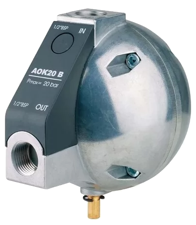
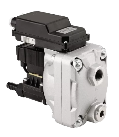
CONDENSATE DRAINS
Model |
ProductID |
Type |
Max compressor capacity
[m³/h] |
Working pressure min–max
[bar] |
Temperature min–max
[°C] |
Inlet-outlet connection |
Feed voltage
[V] |
G 1/2 |
04176 |
mechanical float drain |
5400 |
1.6 ÷ 1.5 |
65+ ÷ 1.5+ |
G 1/2 - G 1/2 |
----- |
G 1/2 |
04177 |
electronic timer-controlled drain |
9000 |
1.6 ÷ 1.5 |
65+ ÷ 1.5+ |
G 1/2 - G 1/2 |
24–230 V |
G 1/2 - 50 bar |
04178 |
electronic timer-controlled drain |
9000 |
4.0 ÷ 1.5 |
65+ ÷ 1.5+ |
G 1/2 - G 1/2 |
24–230 V |
UFM D05 |
04179 |
electronic water level-controlled drain |
300 |
1.6 ÷ 0.8 |
60+ ÷ 1.0+ |
G 1/2 - G 1/4 |
24–230 V |
UFM D10 |
041710 |
electronic water level-controlled drain |
600 |
1.6 ÷ 0.8 |
60+ ÷ 1.0+ |
G 1/2 - G 1/2 |
24–230 V |
UFM D30 |
041711 |
electronic water level-controlled drain |
1800 |
1.6 ÷ 0.8 |
60+ ÷ 1.0+ |
G 1/2 - G 1/2 |
24–230 V |
UFM D130 |
041712 |
electronic water level-controlled drain |
7800 |
1.6 ÷ 0.8 |
60+ ÷ 1.0+ |
G 3/4 - G 1/2 |
24–230 V |
UFM D30HP
(40 bar) |
041713 |
electronic water level-controlled drain |
1800 |
4.0 ÷ 1.2 |
60+ ÷ 1.0+ |
G 3/4 - G 1 |
24–230 V |
|
Nitrogen Generators | ProductID: 0418
Models:
1) Membrane Nitrogen Generators
2) ADSORPTION NITROGEN GENERATORS
|
Membrane Nitrogen Generators
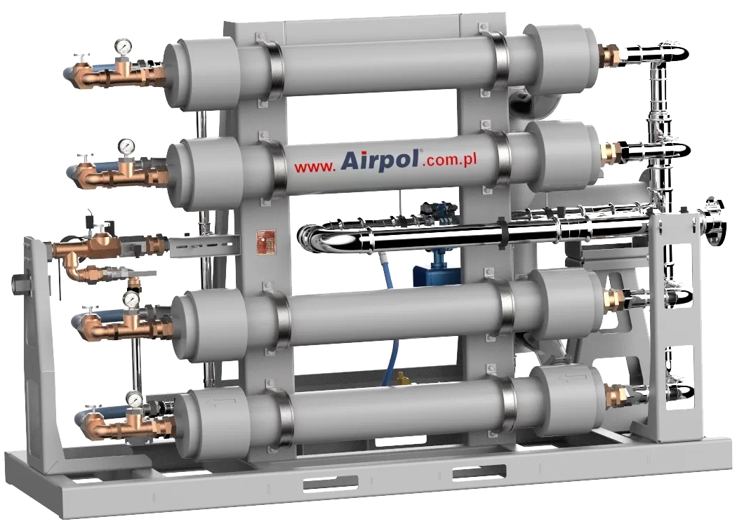
The NGS-M series generators use membrane technology to produce nitrogen. Their purpose is to separate nitrogen from the other components of air, which, in simple terms, is composed of 78% nitrogen, 21% oxygen, and other gases, including 0.9% argon.
The NGS-M nitrogen generators are designed according to each customer’s specific requirements, both in terms of nitrogen purity and installation location (with the possibility of containerized installation). This allows you to optimize investment costs while effectively replacing traditional nitrogen supply methods, such as cylinders or liquid nitrogen. Nitrogen generators are used in various industries, laboratories, R&D departments, pharmaceuticals, and medicine, as well as for inflating tires with nitrogen
|
|
ADSORPTION NITROGEN GENERATORS
The NGS-A series adsorption nitrogen generators utilize adsorption technology on a carbon bed that fills the generator’s columns. These modern nitrogen generators are durable and highly efficient devices. Investing in a dedicated nitrogen generator makes you independent of external suppliers and completely eliminates the need for logistics and cylinder storage. Nitrogen generators are widely used in various industries, laboratories, R&D departments, pharmaceuticals, and medicine, as well as for inflating tires with nitrogen.
|

|
|